intro
Let’s learn everything you need to know about the ER model, ER diagrams, and relation schemas. Understand the difference between them in this ER model vs. ER diagram vs. relation schema comparison article.
When dealing with a database, there are several approaches that you can follow to design and represent its structure. The ER (Entity Relationship) model, ER diagrams (ERDs), and the relational schema are exactly related to that. While they share some common aspects, they differ in their purpose and level of abstraction.
In this article, you will find out more about the differences between the ER Model, ER Diagram, and relational schema. Let’s compare these three concepts!
What Is the Entity Relationship Model (ER Model)?
Entity-Relationship is a conceptual data model used to describe the relationships between objects in a particular domain of knowledge. In detail, the ER model is typically used to describe the structure of a database.
The ER Model consists of the following three main components:
When it comes to databases, the ER model allows you to represent the structure of a database at a high level of abstraction. In particular, this data model can be used for designing a database, providing a blueprint for implementing a database.
The ER Model is often depicted graphically using Entity-Relationship diagrams. Let’s learn more about them.
What Is an Entity Relationship Diagram (ERD)?
An entity relationship diagram (ERD) is a graph based on the ER model. ER diagrams can be used to visually represent the structure of a database. Thus, the purpose of an ERD is to help stakeholders understand how entities in a database are related to each other.
In an ERD, the three ER main components are visually depicted as below:
Even though there are several notations accepted to represent ER, this is what an ER diagram may look like:
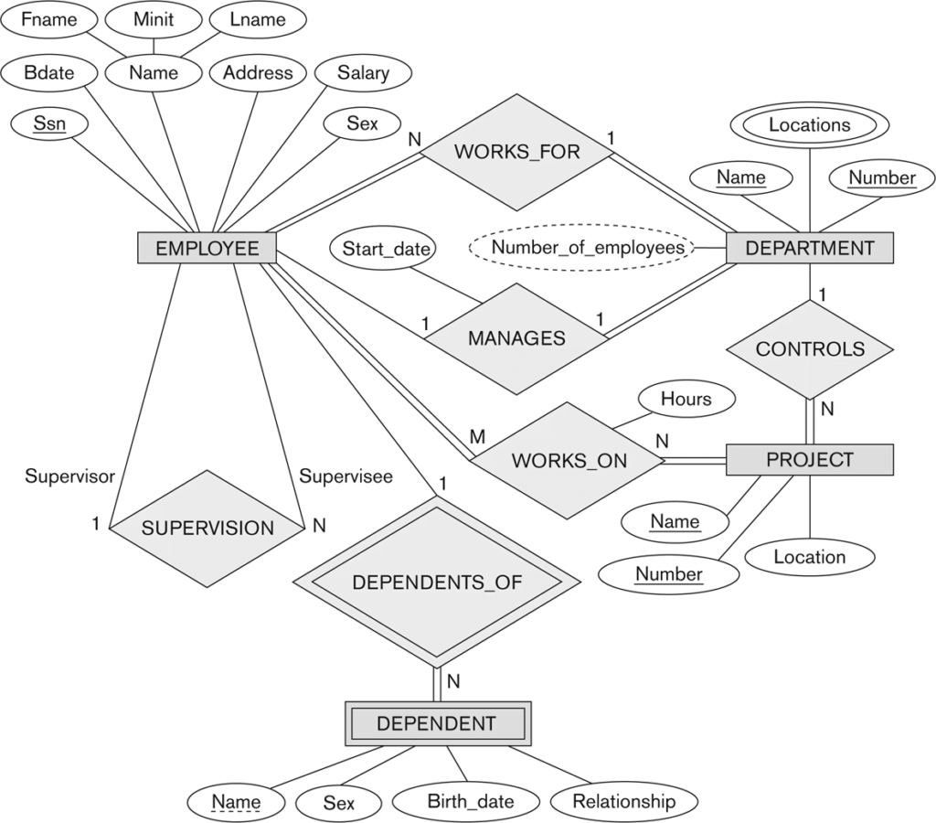
As you can see, ERDs show the entities as boxes and the relationships between them as lines connecting the boxes. Such representation makes it easy to identify design issues or inconsistencies. Thus, entity-relationship diagrams help to develop more accurate and efficient database schemas.
Let’s now take a closer look at what a relational schema is.
What Is a Relational Schema?
A relational schema is a data model for logically representing the structure of a database. A relational schema is a type of database schema specifically designed to represent relational databases. Relational schemas can have a name and consists of the three main components below:
A relational database definition is a collection of named relations, each with its attributes and tuples. In a relational schema, an attribute can also be a key:
You now know what the ER model is, and what ER diagrams and relational database schemas are. Let’s try to understand the difference between the three concepts.
ER Model vs. ER Diagram
The ER model is a data model used to logically represent and describe relationships between real-world entities or concepts, typically when designing a database. On the other hand, an ER diagram is a visual representation of the ER Model that relies on boxes, symbols, and connectors. Both the ER model and ER diagrams work at a high level of abstraction and are independent of the DBMS technology.
In other words, the ER model is the abstract representation of a database structure, while the ER diagram is the visual representation of the ER model. ER diagrams are used to explain and communicate the ER model to others. Thus, you can use an ER diagram to convey your idea of an ER model.
ER Model vs. Relational Schema
The ER model is a conceptual model that defines the entities in a database, the attributes they consist of, and the relationships between them. The entity-relationship model is used to design the overall structure of a database and serves as a blueprint of a database. On the other hand, the relational schema is a logical data model that represents the structure of a database at a lower level. It is used to define a database schema that can be implemented with a particular DBMS. So, a relational schema depends on the features and characteristics offered by the DBMS chosen.
Simply put, the ER model and the relational schema are both used to represent the structure of a database. Yet, they have different purposes and different levels of abstraction. The ER Model is a conceptual model used to design a database, while the relational schema is a logical model to create a specific database schema that can be implemented in a particular DBMS.
If you are looking for an easy and powerful SQL client and database manager, then you've got to try DbVisualizer. It connects to nearly any database.
How to Generate ER Diagrams of a Database
As it should now be clear, ER diagrams play a key role in designing a database. At a glance, they make it possible to understand what tables a database consists of and what the relationships between them are.
Thus, given a database, it is critical to have the ability to generate its ER diagram. Doing it by hand is tedious, cumbersome, and error-prone. That is why you should use an advanced tool, just like DbVisualizer.
DbVisualizer is a powerful, advanced, complete database client that allows you to run queries, create tables, and manage your data visually. Also, it comes with many other features such as the ability to generate ER diagrams automatically. Learn how to use this feature!
Launch DbVisualizer and use it to connect to your target database. In the example below, it will be a PostgreSQL database. However, keep in mind that you can generate the ER diagram on all relational databases extensively supported by DbVisualizer.
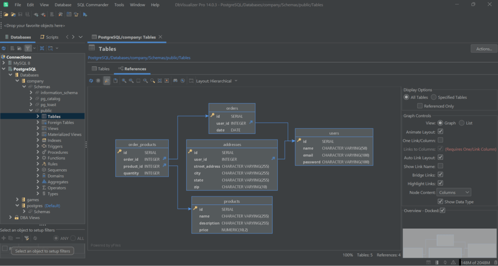
In the “Databases” tab on the right, navigate to the "Table" dropdown menu, right-click on it, and select “Open in New Tab” as in the picture below:

This will open the following tab:

Now, click on “References” to access the ER diagram:
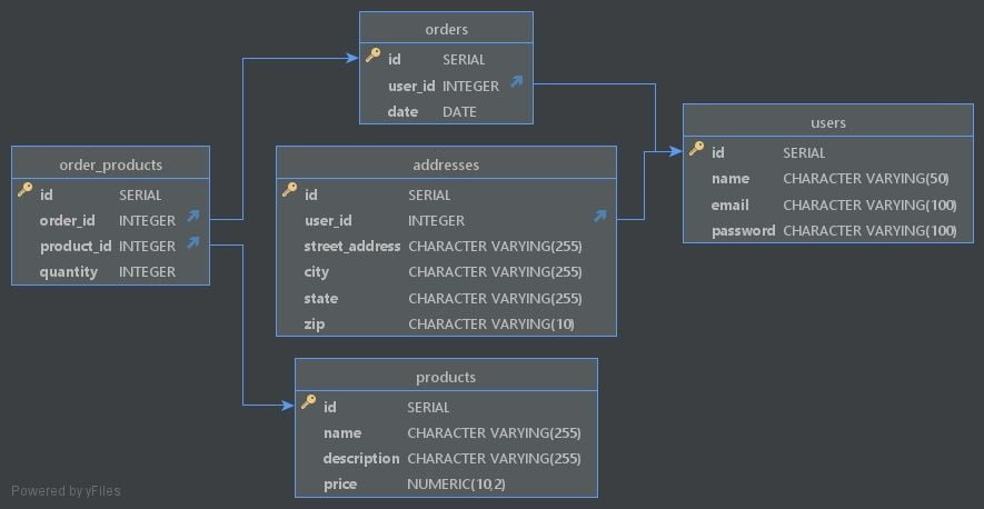
Here, you can explore the reference graph. This visually renders all primary and foreign key mappings to help you understand the relationship between tables. Even though it is not a formal ER diagram, it shares the same purpose.
Note that DbVisualizer allows you to configure the diagram with several options, move the elements, include/exclude tables from it, and much more. Right-click, then click on “Export Graph…” to export the ER diagram as an image file, as below:
Et voilà! Generating and exploring ER diagrams has never been easier!
Conclusion
In this comparison article, you learned what the ER model, ER diagrams, and relational schemas are when it comes to databases. In detail, you saw direct comparisons that allowed you to understand the differences between them. So, you know that the ER model is a conceptual schema to depict a database, an ER diagram (ERD) is its visual representation in a graph, and a relational schema is a low-level representation of the structure of a database.
Also, you learned how useful ERDs are when trying to explain the structure of a database to others or grasp the big picture of a database. Producing a proper ER diagram of a database takes time and is not easy. Luckily, there is DbVisualizer, a fully-featured database client that comes with the ability to automatically generate interactive ER diagrams for you. Try DbVisualizer for free!
FAQ
Let’s now answer some questions about ER, ERD, and relational schemas.
When are the 3 types of relationships in the ER model?
There are three types of relationships allowed in the ER Model:
What is the difference between models and schemas?
In the context of databases, a model is a high-level representation of the structure of a database, while a schema is a low-level representation of the same structure. A database model provides an abstract view of the entities, attributes, and relationships between entities in a database. On the other hand, a schema defines how a database structure can be implemented in a specific database management system (DBMS.)
How can you represent different types of relationships in an ER diagram?
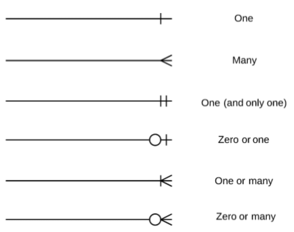
In an ERD, relationships are represented by lines connecting the entities. Then, the symbols at the end of the lines indicate the type of relationship. Take a look at the picture below to see the most common symbols and their meaning:
What is the relationship between ER diagrams and relational databases?
ER diagrams are used as a design tool to create a visual representation of entities and their relationships in a database. Then, this diagram can be used to define the schema of a relational database. Finally, the schema can be adopted to create the physical relational database.
What types of attributes an ER diagram can have?
An ER diagram (ERD) can represent different types of attributes for an entity, including: